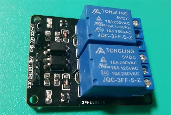
Relay Module
Relay is a switch to control devices which work on ac loads.Ac is alternative current which is used to power ac devices.
Project Description:
In this project we will be turning on a light bulb using realy and serial monitor and know how Relay work.
Steps:
Step 1:
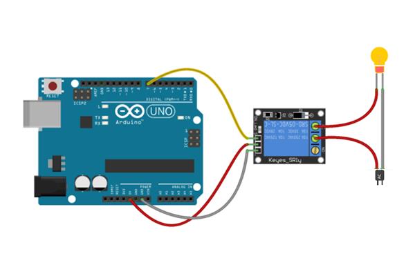
Connecting 5v relay to Arduino
5V relay pin diagram consist of 7 pins we will only be using 3 of them which is:
- GND
- VCC
- IN1
Connections:
- Connect GND pin of relay with any GND pin of Arduino
- Connect VCC with 5v pin of Arduino
- Connect IN1 with pin 7 of Arduino(GPIO pin)
Step 2:
Connecting bulb to bulb holder and really
Connection:
- Connect 2 wire to bulb holder
- Insert the bulb in bulb holder
- Cut one of the two wire in half
- Connect one of the wire to com1 port of relay
- Connect the other wire to nc1 port of relay
What does no1 and nc1 and com1 actually mean?
Com1 which is short form of common1 is the center pole of the relay contacts.
No1 is normally open contact, it’s not in contact with common, and it makes contact with common when the relay is energized.
Nc1 is normally closed contact, it’s in contact with the common when the relay is not energized.
Step 3:
Copy and paste code from below in Arduino IDE
void setup()
{
  Serial.begin(9600);
}

String rx_byte ;
void loop()
{
  if (Serial.available() > 0) {    // is a character available?
    rx_byte = Serial.readString();       // get the character
    if(rx_byte =="1")
    {
    digitalWrite(13,HIGH);
    Serial.println("light on");
    }
    if(rx_byte =="0")
    {
    digitalWrite(13,LOW);
    Serial.println("light off");
    }

}


  } // end: if (Serial.available() > 0)
Step 4:
Turning bulb on and off using serial monitor
Open serial monitor:
- Input 1 in serial monitor for lightning bulb on
- Input 0 in serial monitor for lightning bulb off
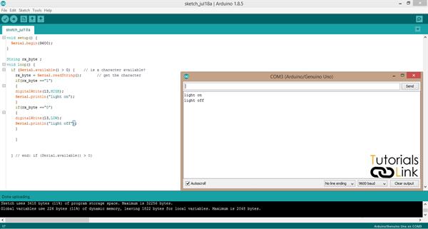
Input given:
The bulb will turn on when you give "1" as input in serial monitor and will turn off the light whenever it receives "0" as input.